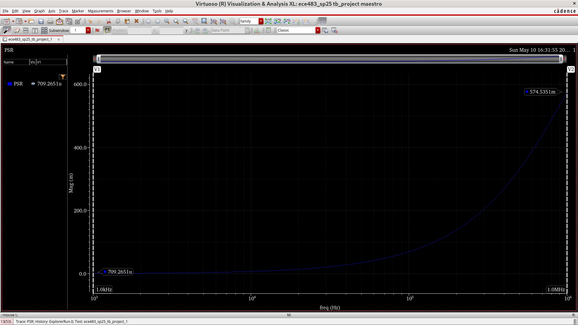
Complete LDO Schematic
Folded-cascode error amplifier, compensation network, PMOS pass transistor, and resistive feedback.
A transistor-level CMOS low-dropout regulator featuring a PMOS-input folded-cascode error amplifier and PMOS pass device. The design applies gm/ID-based transistor sizing, feedback compensation, and stability optimization to achieve robust gain and phase margin across operating conditions.
A 0.6 V reference and resistive feedback establish the 1.2 V output. A PMOS-input folded-cascode amplifier provides high loop gain while avoiding the parasitic penalty of the initial OTA design.
Folded-cascode error amplifier, compensation network, PMOS pass transistor, and resistive feedback.
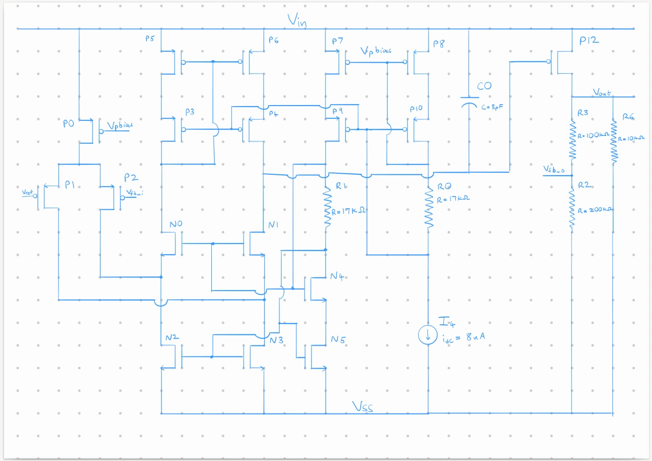
AC loop-gain verification showed approximately 83.1 dB DC gain, 1.27–1.29 MHz unity-gain frequency, and phase margin above 75° across the evaluated load points.
Low-load stability with the output-resistance limiting network active.
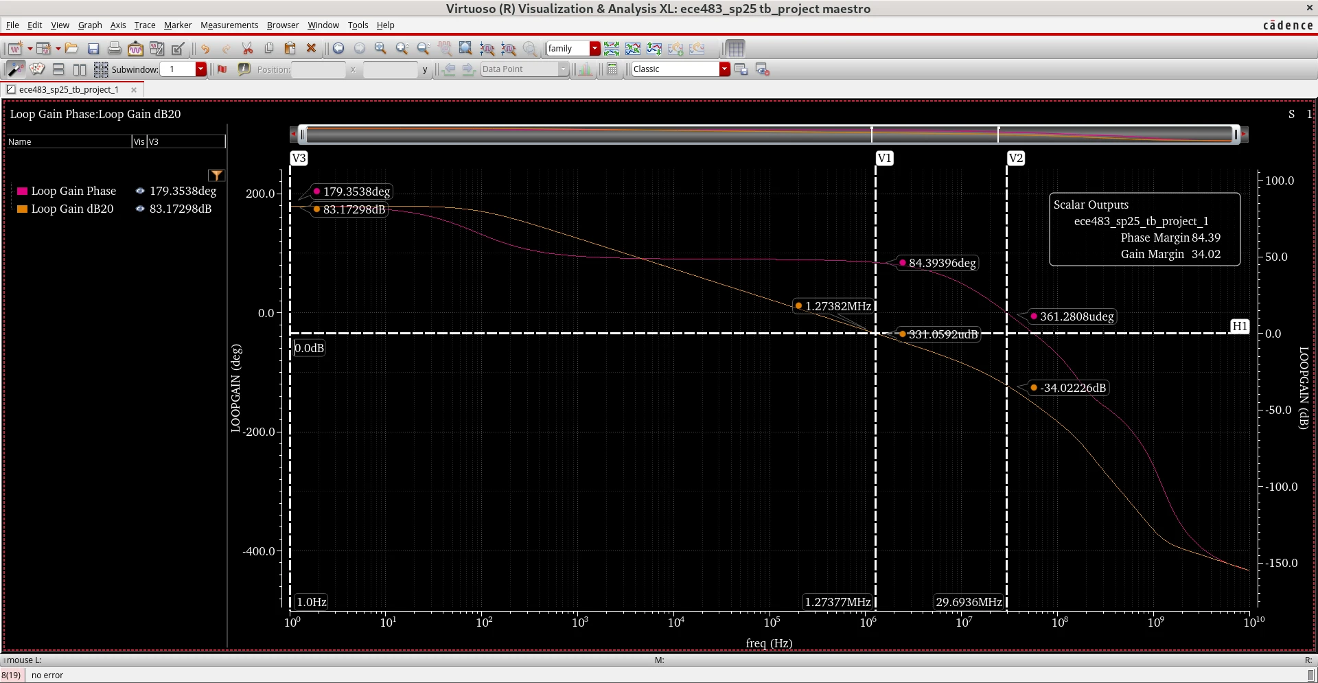
High-load loop response and gain-margin verification.
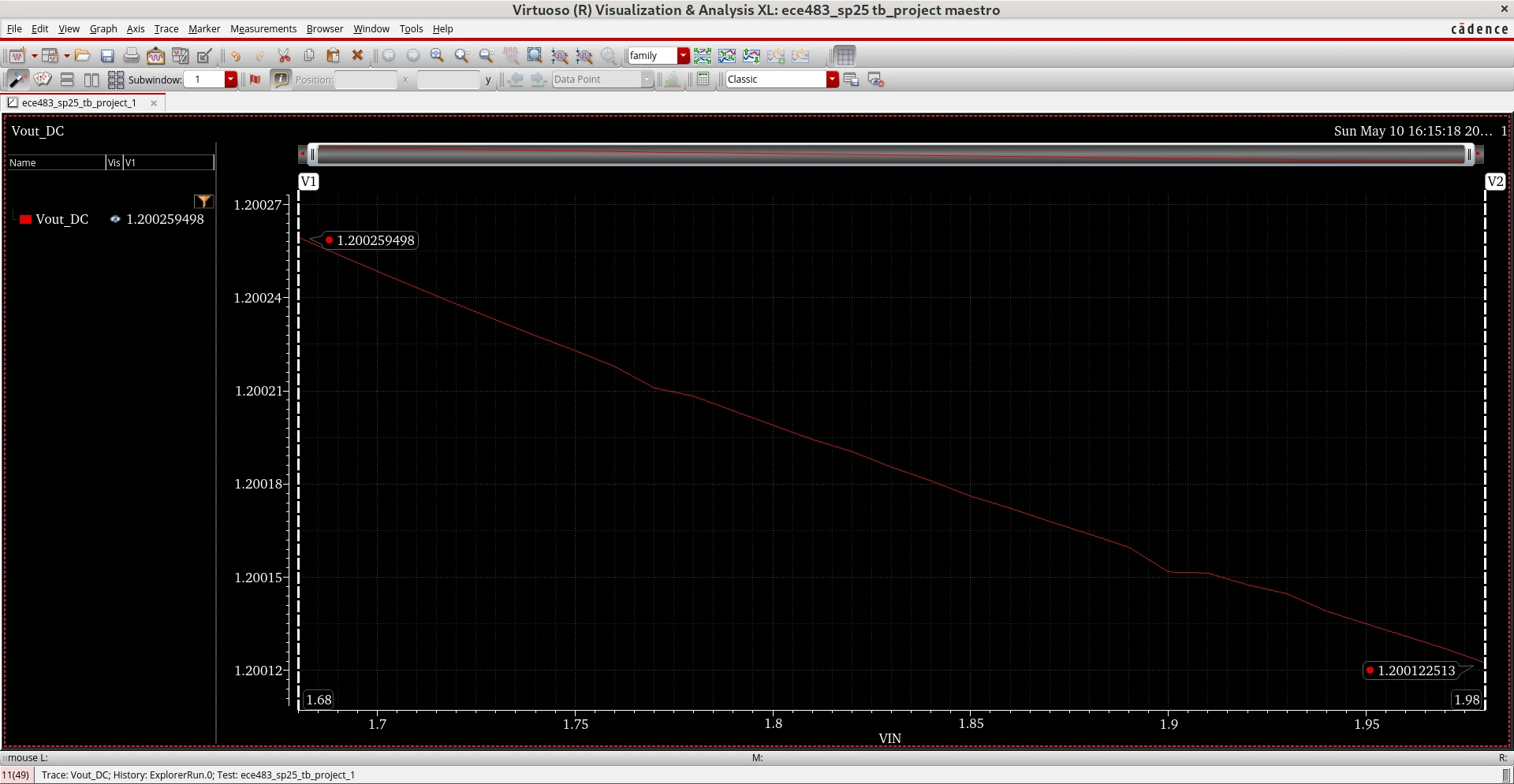
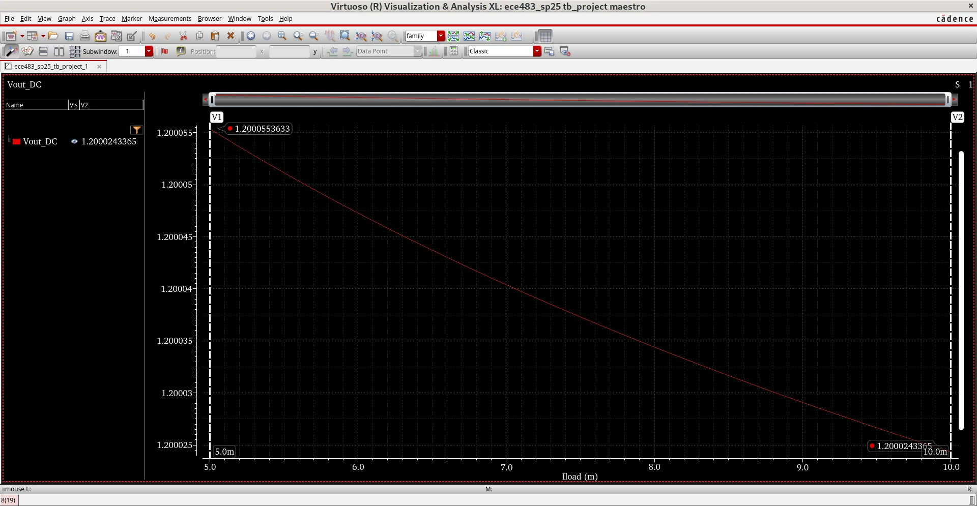
The regulator achieved 6 µV/mA DC load regulation and 479 µV/V / 128 µV/V line regulation at the reported light- and high-load conditions, meeting the project limits.
Output response over the 1.68 V to 1.98 V input sweep.
Regulated output across the evaluated load-current sweep.
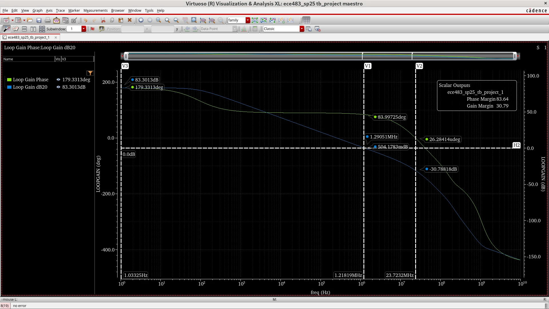
PSR was characterized from 1 kHz to 1 MHz under light-load and full-load conditions to quantify how supply ripple propagates to the regulated output.
Supply-rejection response at 0.1 mA load current.
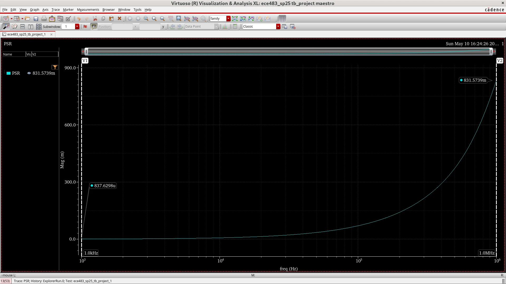
Supply-rejection response at 25 mA load current.